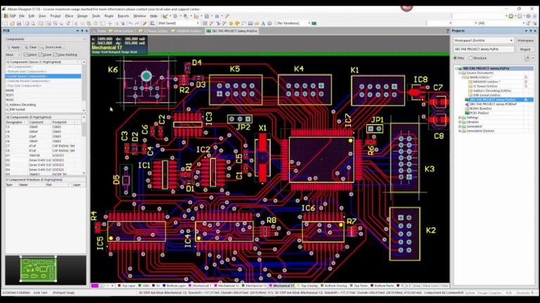

Allegro allows import of Pads Ascii file. Altium allows import of Orcad schematic, Allegro board files, as well as Pads PCB database.

The three tools offer some sort of portability. Similarly it is not advisable to design a high speed board with edge rates in excess of 10 GHz on any tool other than Cadence Allegro. Choosing the right tool for the layout should be at the forefront of PCB layout planning and must never be ignored.Īs an example, using Cadence Allegro to layout a single sided board with a few components will be counter productive when you have tools like PADs and Altium Designer also at your disposal. Although you can use any of these three tools to design virtually every kind of board, it doesn’t mean you should. Each has its own unique capabilities, advantages, caveats and limitations.

Since we’re not at the ideal design scenario yet, we have to make do with today’s available tool technologies.Īmong the most popular PCB layout tools today are Cadence Allegro, Mentor Graphics Pads, and Altium designer. One can only choose the best tool that is most suitable for his/her needs. Today’s PCB layout tools have a combination of some of them, but no vendor has all of those capabilities embodied in one tool. Some design tool parameters that require some experience involve design speeds ranging from a few megahertz (MHz) to over 15 gigahertz (GHz) with board layer counts going from single layer to 50 layers, sometimes more.Īn experienced designer always works diligently with tighter constraints, and uses the more advanced manufacturing technologies paired the right layout tools.įrom the perspective of the experienced PCB designer, compared to the ideal PCB layout tool (See Table 1 below ), most current commercial tools lack key features and attributes described in the chart. In-depth experience using the various PCB layout tools available today is the best indicator of the direction to take regardless of densities, application, or speed requirements. Edit this field to change the track length within the range 0.001mil to 10000mil.As edge rates of logic devices become faster and PCB designs become more advanced and geared towards miniaturization, a number of issues and pitfalls can emerge at the layout stage if you do not have appropriate tools at your disposal to handle your requirements. Length - displays the current length of the track. Edit this field to change the track width within the range 0.001mil to 10000mil.


 0 kommentar(er)
